KM Universal Home ControllerTouchscreen hub + distributed Wi-Fi nodes
Distributed ESP32 control system

One touchscreen. Local I/O. Wi-Fi nodes anywhere you need them.

The KM Universal Home Controller is a 7-inch ESP32-S3 touchscreen hub built to control digital and dimmable outputs locally, then extend those channels around a building through compact ESP32 Wi-Fi output nodes. Channels can be named, grouped, scheduled and mapped without turning the system into a collection of separate apps.

7-inch 800 × 480 touch UIESP32-S3 hubWi-Fi remote nodesDigital + PWM control7-day scheduling
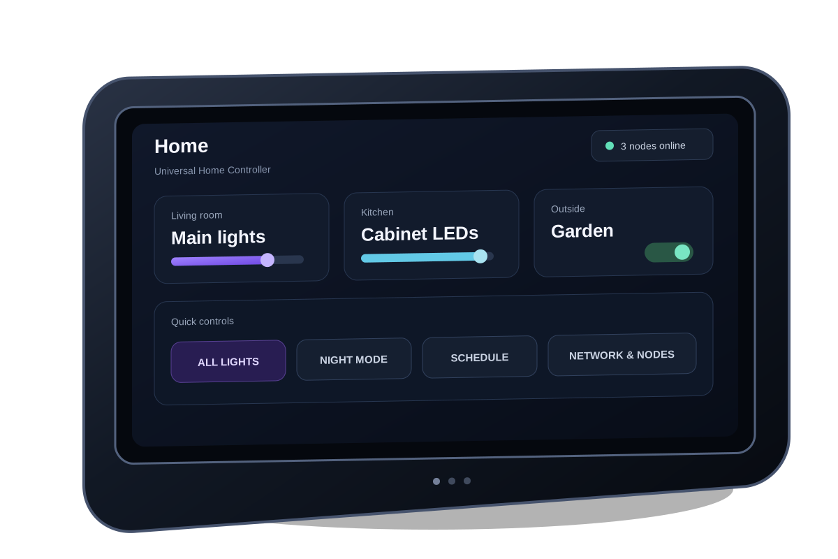
Rendering of the KM Universal Home Controller touchscreen hardware
800 × 480Large capacitive touchscreen interface
ESP32-S3Main controller with Wi-Fi connectivity
Local + remoteMix wired outputs and network nodes per channel
Per-channelNames, switching, dimming, groups and schedules

The controller is the centre of the system

Rather than using the touchscreen as a simple remote, the controller holds the channel layout, room controls, schedules, network configuration and node mappings. It gives the installation one consistent interface while the actual outputs can be beside the screen or somewhere else on the Wi-Fi network.

7-inch ESP32-S3 touchscreen hub

Designed around the 800 × 480 Waveshare ESP32-S3 touch platform, giving enough screen area for real controls, status and setup pages rather than a phone-sized menu stretched across a panel.

Capacitive touchDirect channel, slider and settings control.
Wi-Fi built inDiscovers and controls remote output nodes.
Local expansionDigital I/O and PWM/dimming interfaces can live at the panel.
Persistent setupNames, mappings and controller settings survive restart.
Built for a complete installation

The UI is organised around channels and rooms, not individual GPIO numbers. A channel can represent a light, LED strip, relay, fan enable or other controlled circuit and can be assigned to the most appropriate local or remote hardware.

Master controlGlobal on/off with per-channel control beneath it.
Editable channelsUse meaningful labels instead of fixed output names.
GroupsOperate related outputs together.
PIN / display settingsLock, brightness and sleep options for wall-panel use.

Remote nodes put the outputs where the load is

A remote output node is a classic ESP32 running the KM node firmware. After Wi-Fi setup it operates as a network output device for the touchscreen hub, allowing a controller in one location to switch or dim hardware in another without running every control cable back to the screen.

Controller rendering

Touchscreen controller

Stores the UI, channel assignments, schedules and node mappings. Sends live output commands across the local Wi-Fi network.

Local Wi-Fi
Control + status
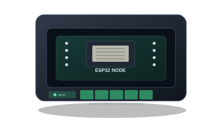
Rendering of an ESP32 remote output node

Remote output node

Receives channel commands and drives configured digital or PWM outputs beside the equipment being controlled.

Simple commissioning

The node starts in setup mode until Wi-Fi is configured, then restarts as a station on the installation network. The controller can discover nodes and assign their outputs to channels from the touchscreen.

Scale without changing the interface

Add output nodes where more channels are needed. The touchscreen still presents one consistent set of rooms, names and controls, while the physical outputs can be distributed around the property.

What it can control

The controller produces low-voltage logic/PWM control. The connected interface hardware determines the load: relay or contactor interfaces for switched circuits, MOSFET drivers for DC loads, or other suitable isolated drivers for the equipment being controlled.

01

On / off circuits

Digital channels for relay modules, contactors, enable inputs and other binary loads.

02

Dimmable DC lighting

PWM channels for suitable MOSFET drivers, LED strips and other low-voltage dimmable loads.

03

Fans, pumps and auxiliaries

Use appropriate driver hardware to switch auxiliary devices or provide a variable control signal where supported.

04

Groups and master states

Link related channels so an area can be operated together while retaining individual control.

05

7-day schedules

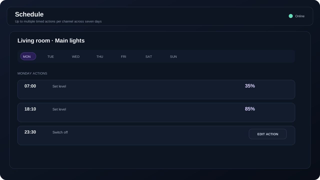
Up to five timed actions per day, per channel, for automatic switching and level changes through the week.

06

Mapped remote I/O

Assign a channel to local hardware or an output on a discovered Wi-Fi node instead of wiring every load to the hub.

Electrical interface: ESP32 and expander pins are control signals, not load outputs. Mains and higher-current circuits require correctly rated relay, contactor, SSR, MOSFET or isolated interface hardware with suitable protection and enclosure.

Hardware overview

The page now documents what belongs in the controller and what belongs in a node, so firmware installation is tied to the correct hardware rather than presented as two anonymous ESP32 downloads.

Universal Home Controller

Main wall / panel interface
ProcessorESP32-S3
Display / touch7-inch 800 × 480 panel with GT911 capacitive touch
Shared I²CSDA GPIO 8 · SCL GPIO 9 on the current controller hardware
Network roleWi-Fi controller / hub for remote nodes
Local digital I/OPCF8574 expander at 0x21, active-low in the current build
Local dimmingI²C PWM/output slave at 0x42 for dimmable channels
Firmware imageKM Universal Home Controller full ESP32-S3 image

Remote Output Node

Distributed output hardware
ProcessorClassic ESP32
Network roleSetup AP until configured, then Wi-Fi station for normal operation
OutputsConfigured digital and PWM-capable ESP32 pins
Typical interfacesRelay boards, MOSFET drivers and logic-level control inputs
PlacementNear the load, panel or room equipment to reduce control cabling
Recovery setupBOOT control can be used to return the node to configuration / recovery mode
Firmware imageKM Remote Output Node factory image v1.0.3

Controller interface and hardware views

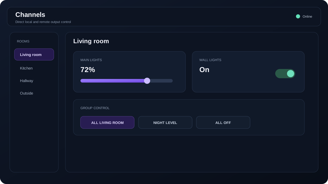
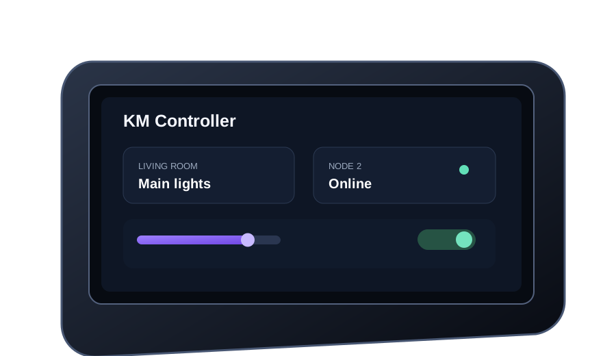
More visual coverage of the system: channel control, network/node mapping, scheduling and the hardware itself. These supplied renderings can be replaced one-for-one with real photographs or screenshots later without changing the page layout.

Install or recover the firmware

The browser flasher remains available, but it now sits inside the product page. Use Chrome or Edge on a desktop computer, a data-capable USB cable and the installer that matches the device.

ESP32-S3

Universal Home Controller

Complete touchscreen hub image including bootloader, partition table and controller application.

ESP32-S3Full imageClean installation
Open this page in desktop Google Chrome or Microsoft Edge and use a USB data cable.Open the installer from a secure HTTPS address.

A clean install can erase stored controller settings.

ESP32

Remote Output Node

Complete factory/recovery image for the classic ESP32 node, including bootloader, partition table, OTA boot data and application.

Classic ESP32Factory image v1.0.3Offset 0x0
Open this page in desktop Google Chrome or Microsoft Edge and use a USB data cable.Open the installer from a secure HTTPS address.

Use this node image only with a classic ESP32 board, not ESP32-S2 or ESP32-S3.

1

Connect

Close serial tools, connect the correct board with a USB data cable and power it from the computer.

2

Select port

Press the matching install button and select the ESP32 serial device shown by the browser.

3

Flash and restart

Keep the cable connected until the installer completes, then allow the controller or node to restart.

Manual BOOT modeIf connection fails, hold BOOT, tap EN/RESET, then release BOOT when the installer connects. After flashing, tap EN/RESET once to start normally.